Since quite some years I was searching for a payable high quality monitor controller which would fulfill the following requirements:
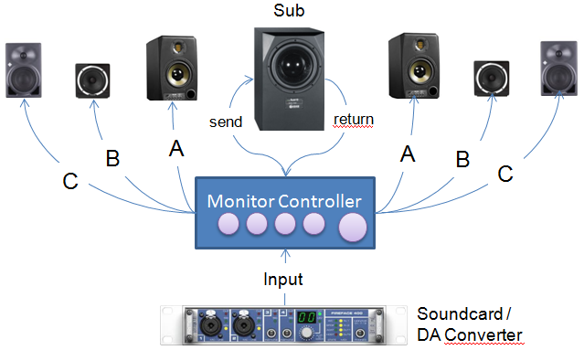
- 1 x stereo audio input (from DAC)
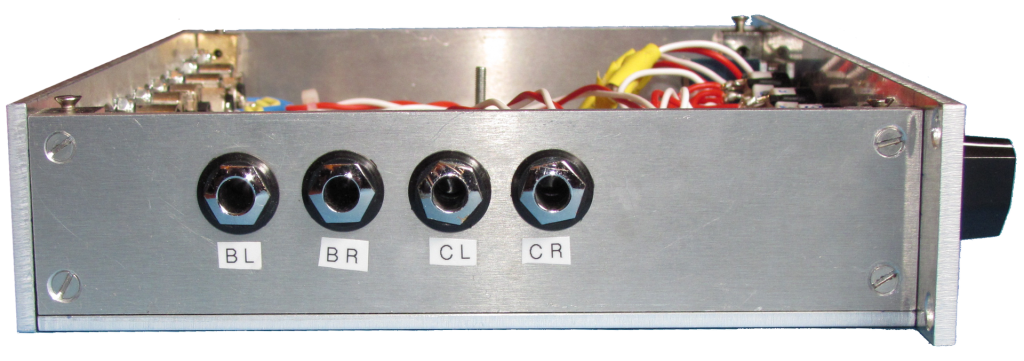
- 3 x stereo audio output for 3 different pairs of speakers/monitors
- 1 x stereo audio send to / receive from sub
- Big handy volume knob
- Mono / stereo / reverse mono switch
- Overall passive and balanced (XLR) design
- Metall case / EMC-safe/compatible
- High overall audio quality, means: controller shall not color or affect the frequency spectrum and stereo image
- Usage of high quality components (especially attenuator, XLR sockets, etc.)
There are many controllers on the market ranging from low cost stuff like the passive TC Electronic Level Pilot to high end active/passive solutions like the Crane Song Avocet. Unfortunately none of them completely fulfilled my requirements, or they were just way too expensive.
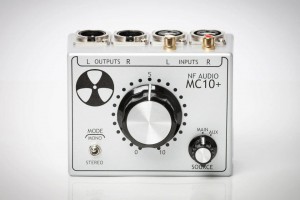
After some research for payable alternatives I stumbled upon a gearslutz thread from NF Audio. NF Audio is a small australian company run by Nick Franklin. See also https://www.facebook.com/NF-Audio-113771681984134/. He builds high quality passive monitor controllers by hand with a moderate price tag. That’s one of his controllers (NF MC10):
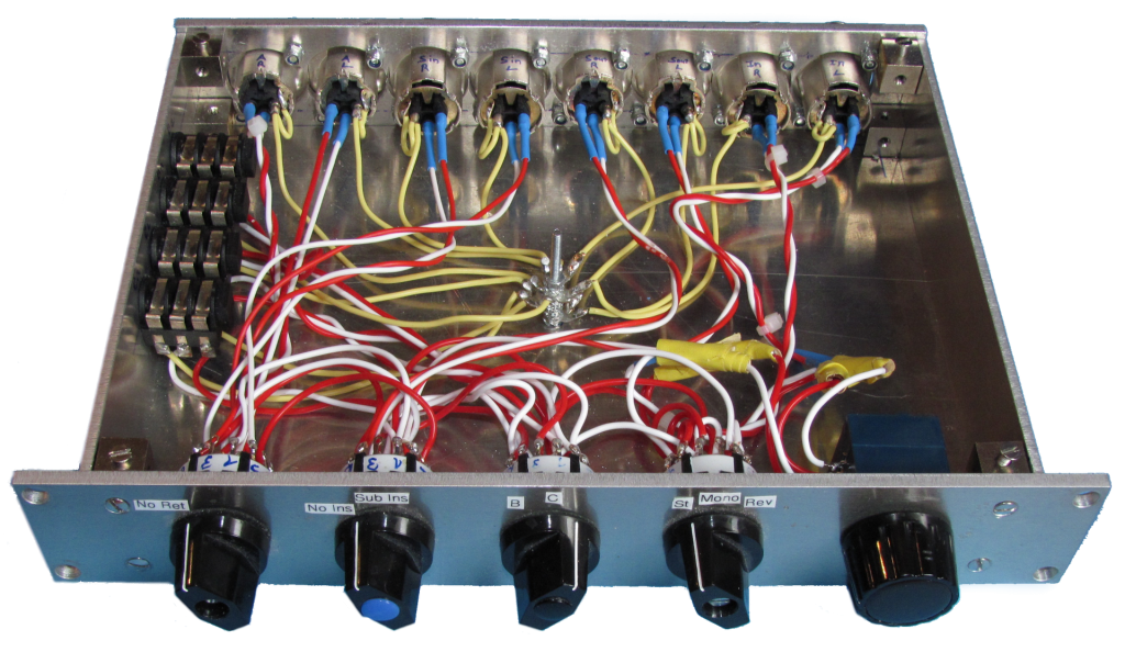
Unfortunately, his product portfolio also didn’t completely fulfill my requirements. So I contacted Nick via email. He’s really a nice guy and gave me helpfull detailed technical hints and support for free. THANKS A LOT NICK ! With help of his support, and a very helpfull article from Rob Squire (See http://www.proharmonic.com/articles/AT78_OTB.pdf), I was able to design my own monitor controller which finally fulfills my requirements. In this article I’ll describe the whole thing in detail. Let’s start with some pictures:
Overview / Pictures

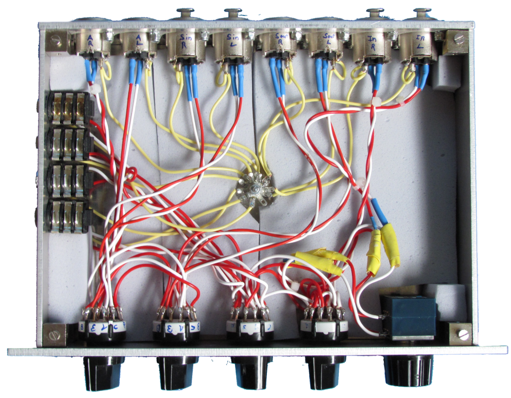
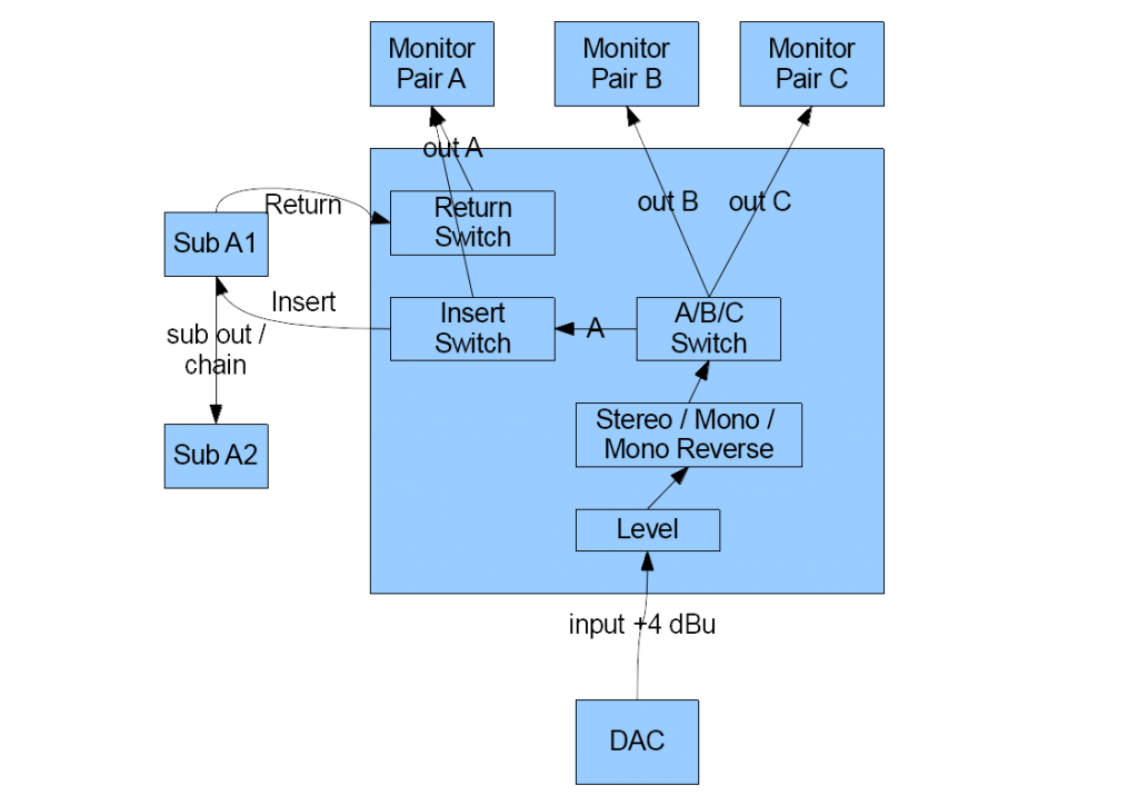
Signal flow and electrical scheme
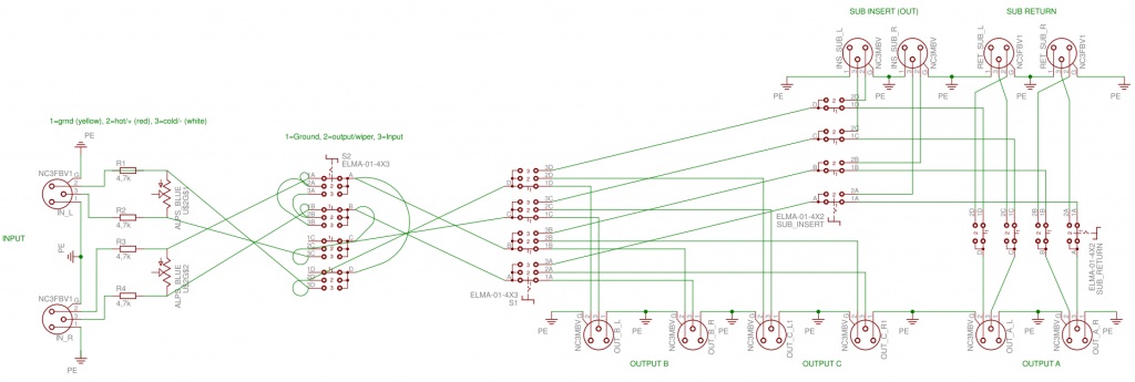
It’s a passive design
There are no active components in the signal path. Why a passive design ? Answer: sometimes the simple things are the best. It seems that for short cable distances a passive design is the best solution: citing Rob Squire: …for cables less than 10m long you’ll have a volume control with a frequency response from DC to over 50kHz and more headroom and a lower noise floor than anything you’ll hope to own that you can actually attach to either end.
It’s a balanced design
All signal ground wires are soldered together (star design). This design still removes hum and noise, but allows for a simplified electrical scheme, lesser wires, smaller potentiometer and smaller rotary switches (less decks necessary).
Hint: the star design is no must have. If you don’t connect the ground wires to the case it’s also ok !
The volume controller
A four deck potentiometer and four resistors are the first components in the signal chain. Together these components build the volume controller, also called attenuator or variable pad. The attenuator dampens the signal level around a maximum amount. (e.g. around -0 dB .. -60 dB).
The minimum and maximum signal level drop heavily depends on the used variable pad. Also does the kind of volume curve (logarithmic / linear) and the accuracy of the stereo signal (ganging of left and right signal path).
Generally, there are two types of potentiometers: stepped and non-stepped. Non-stepped potentiometers, usually conductive plastic pots, allow for finer volume adjustments, but the resistor tolerance is around +/- 20%. Means: the difference between left and right damping curve is higher (especially at minimum/maximum positions).
A stepped potentiometer consists of several discrete damping steps (e.g. 24 or 48 steps). Usually low tolerance resistors (+/- 0,1%..1%) are used for each step. Thus, the difference between left and right channel is minimal. Non-stepped attenuators are often cheaper and smaller. Stepped attenuators – especially those with many steps – are usually more expensive, but are more robust and last longer. The choice is a matter of personal preference.
Moreover, for a balanced stereo design, the pot must provide 4 decks. For a fully balanced stereo design even 6 decks are necessary. In the pictures above an ALPS Blue 10K Log 4 deck version was used. That’s a good pot, but the stereo ganging is suboptimal. Meanwhile I replaced that ALPS pot with a Goldpoint 24 stepped pot and I’m really happy with it. Since I used the Goldpoint the overall stereo image is just better.
Next component in the signal path is the mono/stereo/mono reverse switch
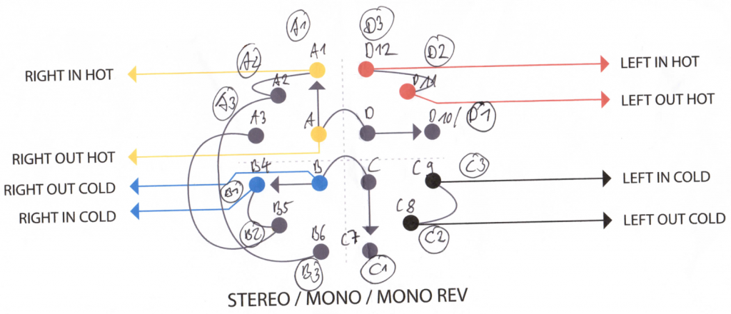
This rotary switch either sums up left and right stereo channels into mono (l and r are the same), or alternatively into mono reverse (= l and r contain only stereo parts). This is very helpfull for checking and analyzing the mix. The wiring scheme looks like this:
Sub insert fx
A special personal requirement was the optional insertion of my sub into the signal path. Means: I wanted to be able to easily switch between sub in and sub bypassed. That’s comparable to the the Focal CMS sub on/off feature: the sub can easily be switched on/off via remote foot switch. In my case I used a rotary switch for that.
The original signal is sent to the sub, which optionally cuts off the sub frequencies using an adjustable highpass filter and returns the resulting signal back to the monitor controller. In other words: the sub may be considered as a classical insert effect.
Finally
I use this controller since many years now, and I’m very happy with it. Which matters most is the simplicity, the overall balanced design and the goldpoint volume controller with it’s perfect stereo imaging. Thus, I really recommend to use a stepped potentiometer as volume controller.


2 Responses to DIY High Quality Monitor Controller